General presentation of inductive sensors
The sensors are now a visible part of today’s vehicles – we could even say that these devices are responsible for the increase in the weight of cars to a small extent. However, this is of minimal importance compared to how much they add to the operation of the passenger car. It can be said without a doubt that sensors, but even without inductive sensors, a car today is immobile. The article below shows how this latter group contributes to our ability to travel.
Historical overview
It is important to note that although we present the various inventions from an automotive industry perspective, the importance of the various sensors far exceeds the limits of vehicle technology.
The first proximity switch was introduced in 1958 by the Mannheim laboratory, which was then owned by a company called Pepperl+Fuchs. In fact, it is the time when electronic automation became possible, which is now the basis of almost all industries.
In the 1960s and 1970s, a number of overlapping patents appeared, which quickly began to spread in various industrial sectors. In 1968, the inductive sensor was also patented which we also owe to Pepperl+Fuchs. Originally, it was specifically intended to replace those tasks that previously required a mechanical connection – or were not feasible for that very reason.
Principle of operation
The operation of both inductive and capacitive sensors (we will write about the latter in a separate article later) is based on the principle of an oscillation circuit. The circle has a specific vibration amplitude which changes when an object enters the active zone of the sensor.
The general characteristic of oscillators is that they consist of an amplifier, positive feedback and frequency-determining elements – the latter, in the case of an inductive sensor, is a parallel LC oscillalation circuit.
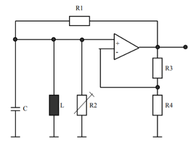
LC oscillation circuit (source: Motofocus)
To understand how it works, it is important to define what determines the frequency of the circuit. This is shown in the following formula:
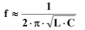
It can be seen from this that the frequency of the oscillation circuit is a function of the inductance (L) and the capacity (C).
In the case of an inductive sensor, the coil of the oscillation circuit is located on a magnetically open iron core, the frequency of the circuit is usually between 100 and 1000 kHz. This vibration creates the changing magnetic field which forms the active zone of the sensor – so it exits the surface of the sensor into the environment.
When a metal object is placed in this active zone, the previously mentioned vibration amplitude decreases, precisely by the amount of energy loss caused by the eddy currents induced in the metal object. Thanks to this, the sensor can decide whether there is something in its active zone.
Although the inductive sensor has energy consumption, this must be kept to a minimum. Today’s sensors consume a few microwatts of power and this has additional advantages in addition to economy:
- It has no significant magnetizing effect on the metal object in the active zone
- There are no reception disturbances
- No heating

Principle connection of an inductive sensor: 1 – Proximity switch, 2 – Oscillator, 3 – Demodulator, 4 – Trigger, 5 – Output signal (source: www.wikipedia.org)
Factors influencing switching
When the sensor detects a specific object, at a special distance, depends not only on the sensor, but also on the object – primarily on its conductivity, since the lower the resistance, the lower the eddy current loss. The nominal switching distance is established with a standard 1 millimeter thick steel plate (St37).
The plate is a square sheet, the sides of which are equal to the diameter of the sensor’s active surface – or three times the nominal switching distance. The larger value of the two must always be taken into account.
In the case of other metals, a reduction factor is applied, which is determined by dividing the connection distance for the given type of material by the connection distance of the St37 steel plate. We can see some examples of this in the table below.
| Material | Conductivity [m/Ω∙mm2] | Reduction factor |
| Aluminum | 33 | 0,35-0,5 |
| Chrome-nickel alloy | 1 | 0,7-0,9 |
| Copper | 56 | 0,25-0,4 |
| Brass | 15 | 0,35-0,5 |
Even the diameter of the coil affects the switching distance. The larger the coil, the greater the switching distance. In addition to these factors, the so-called skin effect, the effect of which is stronger the greater the frequency range and the electrical conductivity of the material.
Installation characteristics, use in the automotive industry
It is not by chance that we only mention metals in the sense of detection, because the inductive sensor can only detect their approach/presence. They typically operate between 10 and 30 Volts, our switching distance is usually 0.8-10 millimeters. They are not very sensitive to contamination, so they can be used in extreme conditions and have a very good service life. The general temperature range is between -25 and 70 °C, but of course there are examples that exceed these.
Since the number of metal parts in a passenger car is significant and there is no shortage of rotating and moving versions, we have good reason to assume that it can be found in many places.
These include, for example, the crankshaft or camshaft encoders, the wheel speed indicators or the speedometer sensor in the gearbox housing. With a good approximation, we can say that the incremental encoders, which are meant to signal the rotation and angular position of the metal parts, are almost without exception inductive sensors in the car or an inductive variant exists.
The end positions of the pneumatic and hydraulic cylinders of tiltable trucks and many other devices are equipped with an inductive sensor, so positioning the piston.
As mentioned earlier, the solution can also be found beyond the automotive industry. Many conveyor belts have inductive sensors to detect the product or product carrier running on the belt. The inductive sensors are so reliable that some kind of metal is often incorporated into the product carrier tray, which is otherwise made of a non-metallic material, in order to equip the belt system with such a sensor.
If the product itself is metal, the sensor can be used for counting in addition to position and end position switching.
Due to its robustness, cost-effectiveness and its ability to be deployed in extreme conditions, the inductive sensor is still one of the most commonly used types today and this will not change in the foreseeable future.
Source:
https://realpars.com/inductive-sensor/
https://www.cncpart.hu/induktiv-szenzor-mukodese
https://www.controlengeurope.com/article/20839/Fifty-years-old–the-proximity-switch.aspx
https://en.wikipedia.org/wiki/Inductive_sensor
https://en.wikipedia.org/wiki/Inductive_sensor#/media/File:Budowa_czujnika_indukcyjnego_(ubt).svg