Factors influencing the heating of the alternator and their effect on the evolution of design solutions
In automotive applications, the primary purpose of the alternator is to meet the electrical demands of installed equipment and to recharge the battery. In motor vehicles, the amount of installed equipment is growing steadily, and the consequence is increased consumption of the electricity supplied by the alternator. Increasing the role of automation and systematically improving the comfort of vehicle users are the most important motivators for the changes taking place. In some cases, a single alternator cannot cover the full electricity demand and, in such cases, additional alternators are installed, for instance – in buses. With regard to 12-volt systems – while in the late 1950s the power of the largest alternator was 600W, it is now around 3,000W and is not expected to exceed this value in the near future.
One of the important factors limiting a further increase of power is the amount of heat released during conversion of mechanical energy to electrical energy. The main factor causing heat generation is the current flowing through the stator winding and the rectifier diodes. The alternator temperature rise depends on the generated heat dissipation rate. The temperature inside the alternator will stabilise at a value corresponding to a situation where the amount of heat released is equal to the amount of heat dissipated.
In modern alternators, the permissible temperature depends on the thermal resistance of the weakest component used, and usually does not exceed 200°C. Given that the alternator is usually mounted to a hot engine housing, the cooling air is close to the temperature of the internal combustion engine. At present, it is assumed that the cooling air temperature can be 130°C, which in consequence causes the permissible alternator temperature rise to be significantly limited. Reliable operation of an alternator depends on its design allowing a considerable amount of heat generated inside to be effectively dissipated outside. Initially (until the 1970s), alternators had an external fan as shown in Figure 1, but this method of cooling at increased load currents proved inadequate.
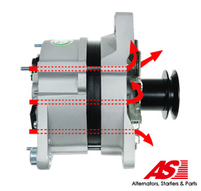
Figure 1 Initial method of cooling the interior of the alternator. Photo by AS-PL
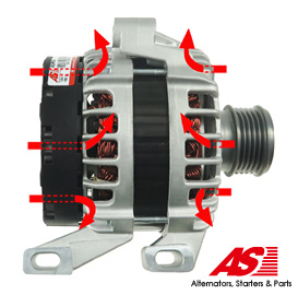
Fig. 2 Method of cooling modern alternators. Photo by AS-PL
The following years saw a complete change in the cooling method. Instead of an external fan, two fans were used by placing appropriate blades on both sides of the rotor (Figure 2). This change, along with the openwork casing, facilitated the flow of cooling air. This type of design is known as compact (fig.3).
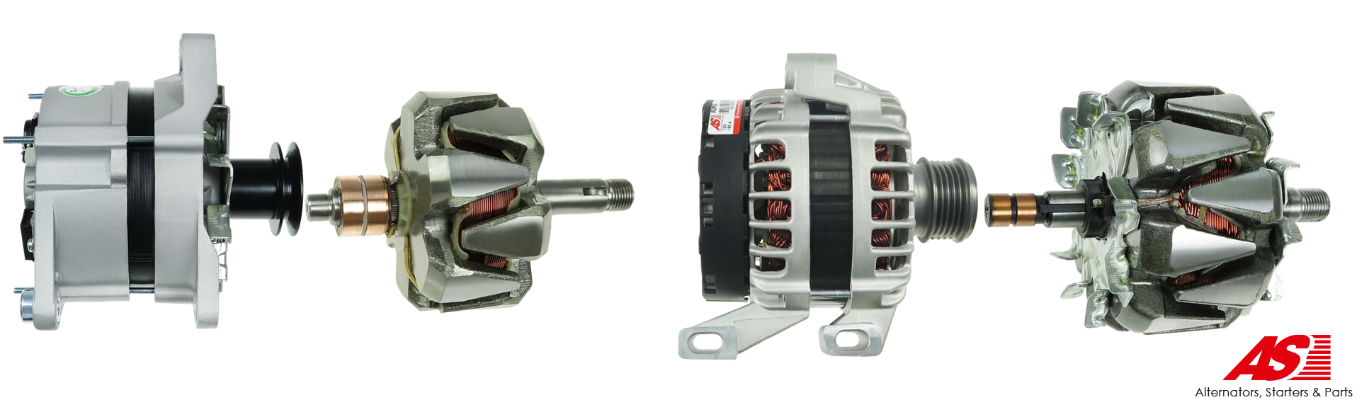
Fig. 3. The most important evolution in the design of alternators and their rotors. Photos by AS-PL
The alternator design continues to evolve. This also applies to stator winding methods and rectifying radiator design. While the heating of the alternator is hardly a surprise, the magnitude of the heat released can be a
cause for surprise. The efficiency of commonly used alternators varies between 60% and 75%, and this means that no less than 25% to 40% of the mechanical energy extracted must be additionally lost to generate the required electricity. Currently, some recent alternator designs, thanks to numerous additional modifications, achieve efficiency of about 80%.
The manner of mechanical energy consumption by the alternator is shown in Fig. 4. For the estimated calculations, a currently used and manufactured alternator with a rated voltage of 12 V and rated current of 140A was selected, whose catalogue efficiency according to the manufacturer’s data is not less than 65%. Based on numerous publications and own experiments, the following conclusions can be drawn:
• Approximately half of the electrical energy produced by the alternator is lost through the heat generated within;
• The most heat is released in the stator windings;
• The diodes in the rectifier bridge give off a significant amount of heat;
• Unexpectedly high energy losses in occur the iron – that is, in the metal part of the stator.
Energy losses during processing are always a consequence of the design solutions adopted. Due to the mass production of alternators, the choice of design is fundamentally influenced not only by the conversion efficiency, but above all by its ease of manufacture and the cost of production. All of these findings have a significant impact on alternator design solutions. The greatest energy loss is due to the heating of the stator winding. Economic considerations and size limitations have led designers to assume a relatively high current density in the stator windings.
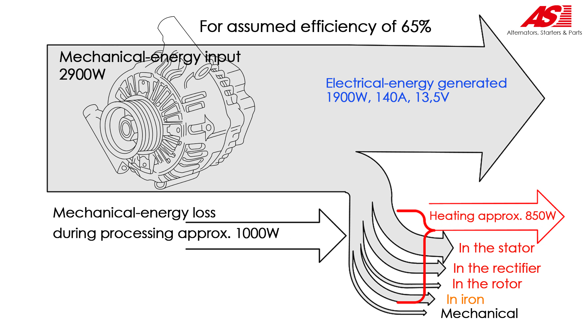 Fig. 4. Energy conversion losses. AS-PL
Thanks to the introduced constructional change, the blades placed on the rotor provide better cooling of the side parts of the stator windings protruding above the rotor blades (Fig. 3). The more intense air movement also cools the diodes in the rectifier. A rectifying diode is not a perfect rectifier. There is a voltage drop across each diode during current conduction. At any time, the load current flows through at least two diodes. For the alternator in question, the heat released in the rectifier corresponds to a 280W heater.
In a stator, heat is generated not only in its windings but also in the metal core itself. An attempt to reduce the iron loss also has consequences in stator design. The metal part of the stator is part of the magnetic field circuit produced by the alternator’s moving rotor. In individual fragments of the core, the magnetic field systematically changes its direction with a frequency of up to several hundred hertz (at 3000 rpm motor speed the frequency is about 600Hz). This alternating magnetic field causes energy loss for over fluxing and results in eddy currents that depend, in the second power context, on the frequency. The practical use of this phenomenon is commonly used in induction hobs in our homes. To obtain the needed thermal effects, a field variation frequency of 24kHz was used there.
In the case of an alternator, the heat generated is undesirable. If the stator core was made of solid material (like in a frying pan), the energy loss and its heating would be far greater. In order to limit these phenomena, the stator core is made of thin sheets, electrically insulated between one another. The magnetic flux flowing within the thin sheets causes much smaller eddy currents, reducing the unavoidable energy losses to a large extent. To further reduce eddy currents and deteriorate electrical conductivity, the sheets are made from a special grade of steel containing an increased content of silicon compounds. This way of limiting the effects of eddy currents is used in all AC magnetic circuits.
The search for better solutions continues. Leading alternator manufacturers already have products in their catalogues with efficiencies approaching 80%. Any success in this area is part of a global trend towards better care for the environment. Higher efficiency means lower fuel consumption. In an effort to reduce fuel consumption, overrunning clutch drive wheels have been used in alternators for many years, utilising the kinetic energy of the alternator rotor when the speed of the internal combustion engine is reduced. In recent developments, the alternator can assist the internal combustion engine at rapid acceleration, assist braking and use the braking energy to recharge the battery, and can start the warm internal combustion engine instead of the starter.